Some common questions we have been asked are broken down into the broad categories below. If you have a question relating to our chargers, please feel free to submit it via the support page, we’ll try and answer it.
What is the diagnostic port for?
The port offers enhanced information on the status of the ports. In addition, for v2 units, there is a Windows application to monitor the device's status.
For v1 units, the diagnostic port will show the port's status, if a device is attached or removed, and the power drawn per port in real-time. It emulates a serial port over USB, so it is universally supported. The port settings are 57600, 8 bit, No parity, and 1 Stop bit (8N1).
Pressing any key brings up a menu, offering more details and allowing inputting and assigning custom profiles to the ports. This enables the supplies to be easily extensible for devices that do not conform to the various standards.
I've seen other USB chargers aimed at GA/LAA that are cheaper.
No doubt, we've seen quite a few too. Some may work OK with your device today, but are they built to the same performance and safety levels? The technical testing requirements these products should go through, given the intended environment, make interesting reading, particularly operating outside the 'normal' ranges. Such as input voltage 50% above normal for 5 minutes, short circuits on all output ports for a minimum of 1 minute, voltage spikes of up to +/-60 volts etc. should not be a problem.
Even if not aiming for the likes of TSO approval, essential protection should be designed into any product given the cost of the devices people want to power and the electrical environment encountered within light aircraft. Out chargers have features to help protect devices as much as possible.
What's wrong with a generic plug-in charger?
Interesting question. Perhaps the question should be, 'is there a generic plug-in charger suitable for use in the air?' Anyway, back to the original question, the answer depends on which of the huge number of units you are talking about. Broadly we have seen several common issues with them; high level of RF interference, poor voltage regulation, especially under load, narrow device support, lack of safety/protection features, and the potential to damage the device under charge because of one (or more) of the above.
Remember, generic plug-in chargers are sold as just that, to be used for short periods to charge a device, with the lower output being needed as the battery charges. So to use one for extended periods can cause issues of its own.
The generic cigarette charger should have been tested for radiated emissions. Unfortunately, not all have been through anything other than very rudimentary testing. Some cheap Chinese ones haven't even had that. None of them is required to have conducted emissions tested, being battery powered.
One of the most common problems is the stated power output. For example, say a generic charger is rated at 3 Amps, when you try to draw close to 3 Amps from it, the voltage drops and fluctuates, often causing it to overheat. Usually, this is combined with being built to identify itself as a particular type of high-power charger, so your device may try to draw as much power as it can. This can damage your device, the charger itself, and be a hazard when in the air.
We looked at a number of them when researching the original problem which led to the development of our chargers. The real issue is simply that they were never designed for use in the air.
What are my fitting options for aircraft?
If your aircraft falls into the Light Aircraft (LAA) or US Experimental Amateur Built (EAB) class aircraft then you can permanently wire the units into the aircraft, with suitable protection for the power feeds the same as any other device, and with sign off according to your local rules. If you have an open cockpit, you can use USB extension cables and tuck the unit in a dry area and fit waterproof USB sockets. Just be aware of the cable limitations given in the USB Charging FAQ.
For EASA certified aircraft, permanent installation is permitted under Issue 4 of the CS-STAN regulations. Details of what is required to achieve this are here.
Can I run a unit from a battery pack?
Yes, no problem. The supplies will work happily if the input voltage is between 11v and 30v and sufficient capacity.
What does a micro-controller give me?
The obvious thing you can see is the status lights, which let you know what is happening on each port. Behind the scenes, it manages the USB ports for supplied current, faults, etc. The basic principle within the units is that the USB ports are powered off (i.e., they will supply no power) until a device is actually detected as being connected. Only then does the unit actively look to find the most suitable power profile for the device. Once a device is in a steady charging state, the status light goes green to show all is OK. The port is then continuously monitored for faults or the device is disconnected.
As there are an ever-expanding number of power-hungry devices, it also enables the supply to be extensible. Should a device come along that it cannot correctly handle, additional profiles can be added to the supplies via the diagnostic port.
Can I use USB extender cables, to mount USB sockets around an area?
Yes, you can, but you need to be careful.
The extension cable should be no longer than 1m and you cannot use any type of USB extension cable. The only recommend ones must have at least 20AWG (or 0.5mm cross section) cables on the +5v and GND wires. Commonly these will be identified as 20/24 or 20/28 cables (20AWG for the power and 24/28AWG for the data). This is needed to ensure, at higher charging currents, the voltage doesn't drop too much in the cable. We don't specify this for our own amusement, it's basic physics to ensure your device gets the voltage it needs and the cables do not overheat.
You could then, for example, get hold of a USB A to B cable and fit one of these panel mount USB outlets from Neutrik. You can get covers for them too, if required.
What is the power input connector type?
All units need a Molex MicroFit 3.0 connector, specifically one Molex 43645-0200 connector and two 43030-0002 crimp pins for the power lead. This is a latching connector, so it will not vibrate loose in a panel. The positive terminal is the one on the left when looking directly at the back of the unit.
Ideally, when crimping the connections, it would be best if you used a Molex crimp tool (part number 63819-0000).
What is ETFE cable?
ETFE is short for Ethylene tetrafluoroethylene, a cable covering that offers a high degree of corrosion resistance and strength whilst being light. It is often used in aircraft wiring harnesses for these reasons. It also has low fume toxicity when exposed to flame.
The cable is selected for safety. Whilst by no means the cheapest cable type out there, it is the best choice for the intended environment.
My device is slowly discharging when powered, what is wrong?
In the vast majority of cases this will be the lead feeding your device. Breaking this down into two areas;
- USB power cables are designed to be flexible, so contain many strands of very fine wire to achieve that. Over time some of these strands break and lead to poor performance, in effect the cable becomes thinner and so less able to carry power. Try a new cable and see if the problem goes away, but....
- A number of manufactures cables are 'active' these day, there is actually a small chip in the cable to control the power and data. Non genuine cables often have cloned chips and so do not perform anywhere near as well as genuine cables. So if you need a new cable, the best advice is used an original manufacturer one if at all possible.
Why a Smart charger, it’s all just plug and go isn’t it?
Simple answer, no.
More complex answer, there are three main ‘types’ of USB port;
- SDP; Standard Downstream Port, which supplies up to 500mA for powering an attached device with data
- CDP; Charging Downstream Port, can supply/charge up to 1500mA and still have data running
- DCP; Dedicated Charging Port, which doesn’t pass data but can supply power over 1500mA
The signalling of the various types of port is by using the D- and D+ pins, in a variety of combinations, which are often manufacturer specific. In addition to the various voltages there are also the possibilities of a short between the two pins or open circuit. Each manufacturer simply chooses a value to use, there is no common standard within the DCP world. Some devices even want to see an ‘active’ charger, where they perform a handshake too.
When you plug your device in, it also has to work out what type of port it is connected to, which is complex in itself too. A snippet from the specification over how they do that is given below.
My charger is rated in Watts, but you talk about Amps, whats the difference.
Nothing really, they are just different ways of giving the same information.
Watts = Volts * Amps
Amps = Watts / Volts
What is the difference between ’rapid’, ‘standard’, and ’trickle’ USB charging?
Nothing, they are a myth. The USB charging standards dictate that a device can only draw;
- 100 mA prior to charger detection
- 500 mA following charger detection
- up to 1500 mA following the detection of a USB BC1.2 standards compliant charger
If the device detects its own dedicated chargers particular signature it can draw power above 1500 mA. So if your device is ‘trickle’ charging it is because it doesn’t believe it is plugged into the right charger, the charger does not support BC1.2, or the charger cannot cope with the demands of the device.
It’s important to note that regardless of the stated power output of any charger, it is the device that determines how much current it can draw not the charger. So if your device doesn’t believe it is See the question below on how the device detects the charger type.
A generic basic charger and a ‘cheater cable’ is just the same, is it not?
Well, no, not really. Cheater cables try to emulate the a specific companies charger signature, so fool the device into thinking it is plugged into its own charger. Which seems great, unless the charger cannot actually handle the needs of the device, let alone the quality of the cable itself. Then you can get all sorts of interesting things happen.
- The charger may not be able to provide the current the device wants, so normally the voltage drops. This makes charging slower and puts stress on the device being charged. There are a few companies in the UK now specialising in repairing devices with broken charge controllers, as a result of the influx of low quality chargers.
- As well as damaging the device, it can also lead to problems with the charger, overheating and lots of RF interference are the prime examples
Cheater cables are often poor quality, which doesn’t help when you want to pull as much power through them as possible, they are cheap for a reason - You will need to buy a cheater cable for each device you own
- The starting point for the design of the Charge2 and Charge4 was to address the problems that generic cheap USB chargers caused in a light aircraft, details are available here.
How does the device detect what the charger is?
The ‘communication’ is done by a handshake via changing the resistance / voltage levels on the two data pins within the USB connection, in the right sequence and to a strict timeline (measured in milliseconds). A passive charger (such as a cheap plug car style) will probably a hardwired ‘profile’ which is normally a short of fixed set of resistors on the data pins, some chargers do have ICs to support some devices on the market at the moment they rolled off the production line. There are in excess of seven different types of bespoke identification out there at the moment, if you fancy some bedtime reading, pop over to the USB Developers website, it’s all on there. http://www.usb.org/developers/
Charge2 and Charge4 take this a little further by using a micro controller to make emulations extensible, so for future device requirements new devices can be supported. Once we get hold of one of the new devices a custom profile can be created and entered, extending the life of the charger. The problem is that whilst a USB standard exists, anything which wants to charge over 1.5 Amps isn’t supported by the standard, and all the manufactures like to do things differently.
Assuming the charger is correctly built to act just as a charger and nothing else, then your device has to decide if it is plugged into a Charging Downstream Port (CDP) or a Dedicated Charging Port (DCP), the description of what happens is a bit longwinded;
- During Primary Detection the PD shall turn on VDP_SRC and IDM_SINK . Since a DCP is required to short D+ to D- through a resistance of RDCP_DAT , the PD will detect a voltage on D- that is close to VDP_SRC.
- A PD shall compare the voltage on D- with VDAT_REF . If D- is greater than VDAT_REF , then the PD is allowed to detect that it is attached to either a DCP or CDP. A PD is optionally allowed to compare D- with VLGC as well, and only determine that it is attached to a DCP or CDP if D- is greater than VDAT_REF , but less than VLGC . The reason for this option is as follows.
- PS2 ports pull D+/- high. If a PD is attached to a PS2 port, and the PD only checks for D- greater than VDAT_REF , then a PD attached to a PS2 port would determine that it is attached to a DCP or CDP and proceed to draw IDEV_CHG . This much current could potentially damage a PS2 port. By only determining it is attached to DCP or CDP if D- is less than VLGC , the PD can avoid causing damage to a PS2 port.
- On the other hand, some proprietary chargers also pull D+/- high. If a PD is attached to one of these chargers, and it determined it was not attached to a charger because D- was greater than VLGC , then the PD would determine that it was attached to an SDP, and only be able to draw ISUSP.
This actually all means that your device drains then puts some voltages onto the Data pins, looking to see what is there. Depending on what it sees it will make a decision over what type of device it thinks it is plugged into and act accordingly.
So there is USB 1, USB 2, USB 3, and USB 3.1 - what is the difference?
These are all variations of USB protocols, which are faster the higher the number. In terms of power delivery, or charging ability, they are comparable with one another. Any device which has a USB Type A connector (the one found on laptops and PCs worldwide) is compatible with the power delivery of Charge2 and Charge4.
Things will change with the announcement of the new Type C USB connector in August 2014 intended to go with USB 3.1, which is reversible and the same at both ends. A first for the USB specification, it also means that you won’t be able to use a device with a type C connector until your laptops and PC’s are also all fitted with type C connectors. No doubt at some point that will happen, but it will take a while. In the mean time it is expected that devices will be supplied with adapter leads, to go from type C to type A, and normality returns in terms of power delivery. Much like Apple moving from the 30 pin connector to lighting, the device side changes by the host/charger end has remained the same.
There are changes within USB 3.1 for higher power delivery, but for power up to 12 Watts (2.4 Amps) everything is backwards compatible with the previous versions. If you go over 12 Watts then it’s a new ballgame in the charger market, as the voltages go up from 5v to 20v for full 100 Watt power delivery. Of note is that the USB 3.1 introduces a new power delivery scheme ‘USB Power Delivery 2.0’, which co-exists on devices along with the current BC 1.2 standard that Charge2 and Charge4 support, so new devices will still charge fine with a suitable USB lead.
What standards do the units meet?
Currently we are working to standard CE compliance criteria, so it is legal to sell units in EU and most other countries where a bilateral agreement exists (which is virtually everywhere). This involves EMI and RoHS compliance. That said read onto the next question…
Will an aviation certified version be available for EASA aircraft?
Whilst our supplies do not carry a full TSO approval, under Issue 4 of the CS-STAN regulations installation is permitted into EASA aircraft. Our power supplies are designed to meet ETSO-C71 and the testing standards RTCA/DO-160E. Testing of our supplies was carried out by JP Avionics in the Netherlands and their test reports have been accepted by EASA for installation into EASA aircraft. Following an update to CS-STAN our supplies may now be easily fitted into EASA aircraft, details available here.
USB Standards supported?
There are two main USB charging standards; USB Battery Charging specification 1.2 (BC 1.2) and the Chinese telecommunications standard YD/T 1591-2009. The units adhere to both of these standards, and in addition support various manufacturer specific device profiles for where the required current draw exceeds the standard 1.5 Amps available.
Any USB 1.0, 2.0, or 3.0 device shares the same charging standards. USB 3.1 has a totally new power delivery mechanism but is also backwards compatible.
Our chargers have been designed from the outset to the EMC standards for aviation, specifically DO-160E. These standards are aimed at fully certified aircraft and are pretty tight. There is no reason why they should not apply to smaller aircraft, after all, you use the same radio frequencies for communication and navigation as everyone else.
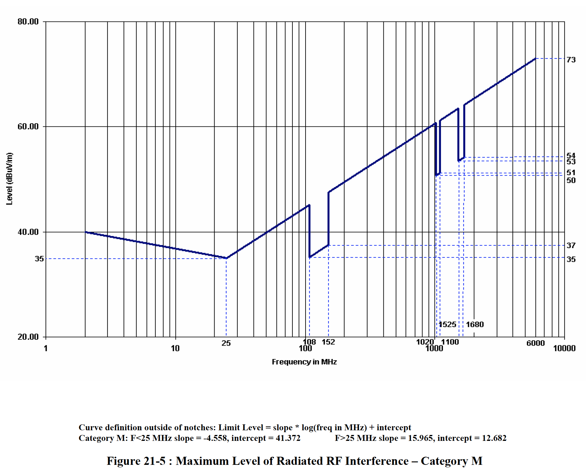
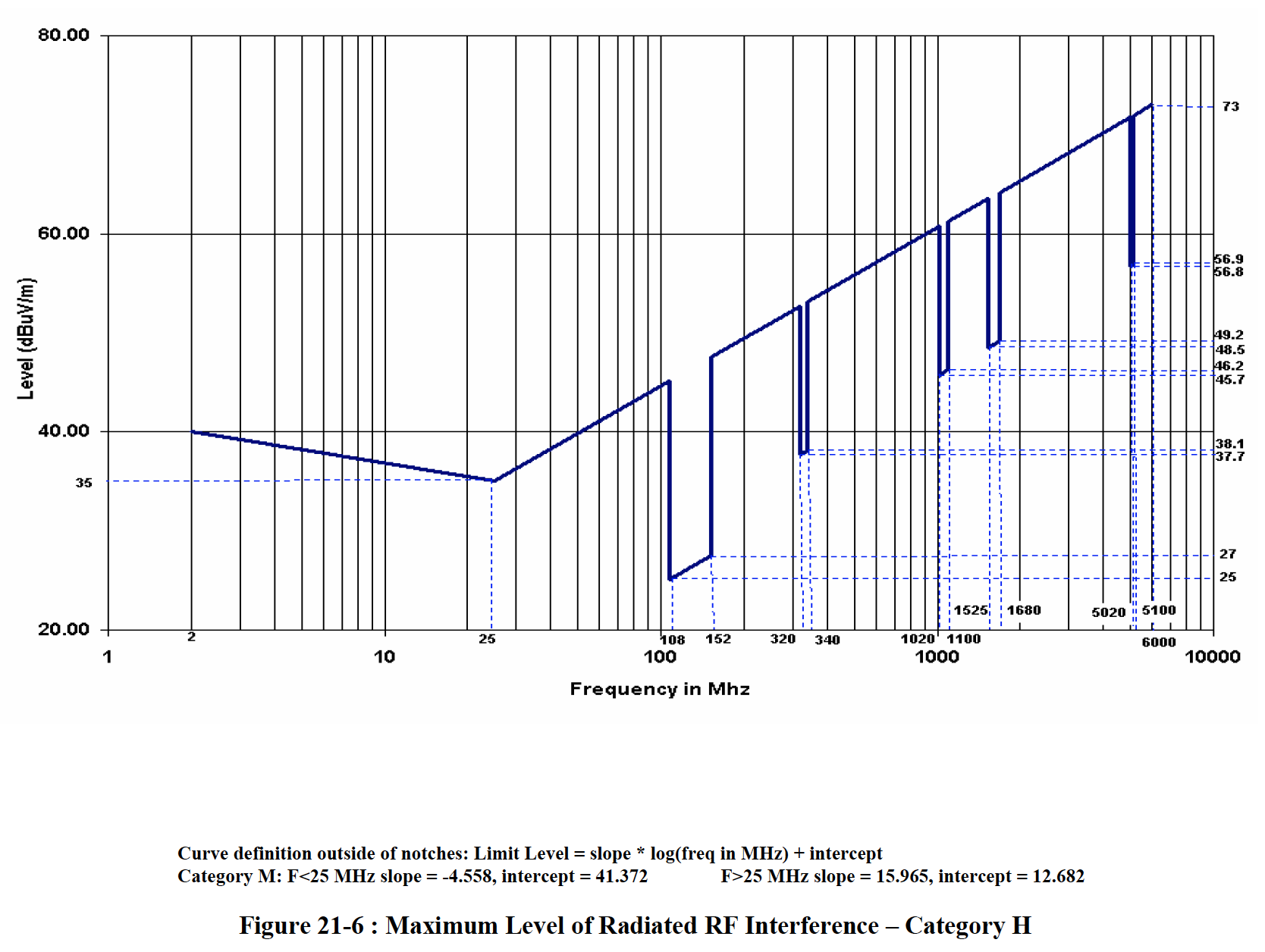
For radiated RF the limits show specific notches that cover communication and navigation frequencies. The applied limits depend on the category of the installation, category M and H are the ones of interest.
Category M is for equipment and interconnected wiring located in areas where apertures are EM (electro-magnetically) significant and not directly in view of radio receiver’s antenna. This category may be suitable for equipment and associated interconnecting wiring located in the passenger cabin or in the cockpit of a transport aircraft.
Category H is defined for equipment located in areas which are in direct view of radio receiver’s antenna. This category is typically applicable for equipment located outside of the aircraft.
Whilst category M is technically the one to use, and these limits were used for the testing, it could be argued that category H applies for small GA-sized aircraft owing to the closer proximity of all the equipment. This isn't a problem, as our chargers can meet these too.
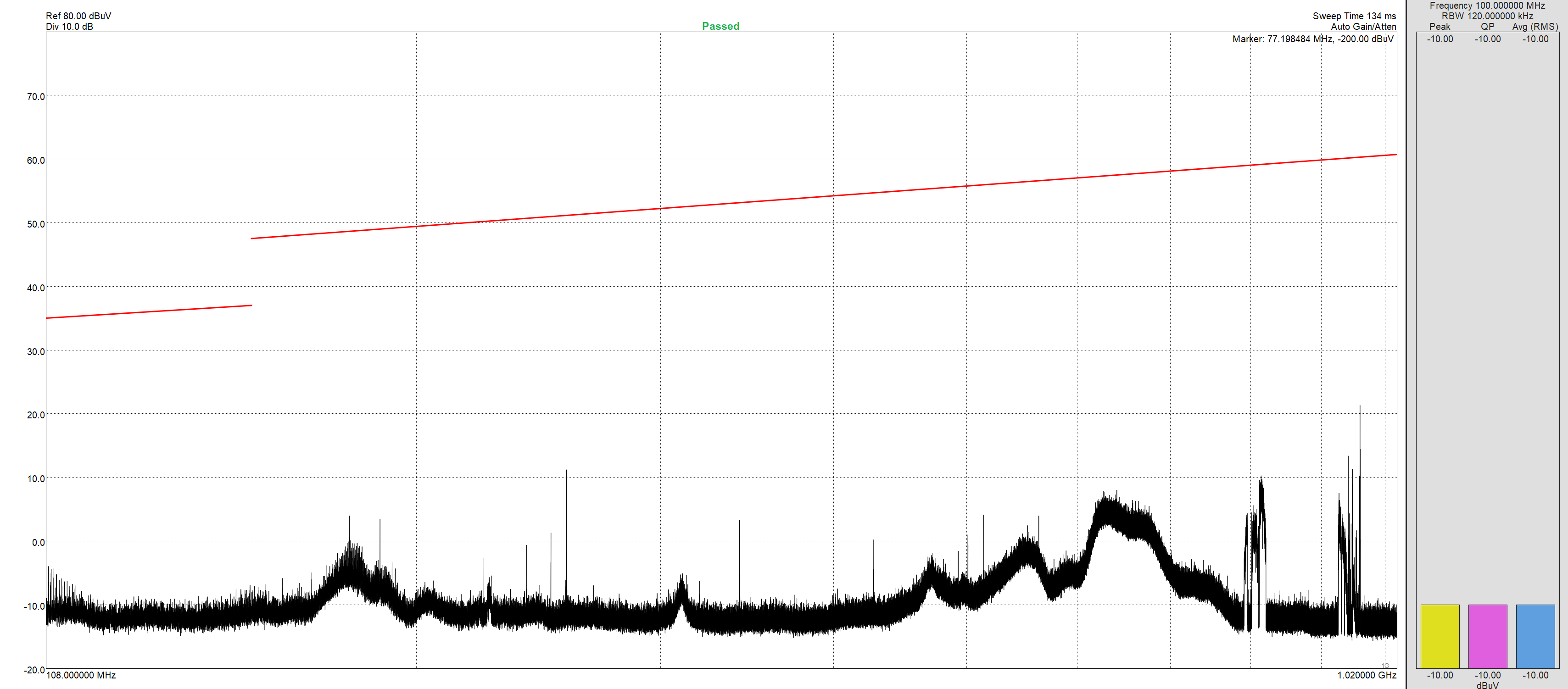
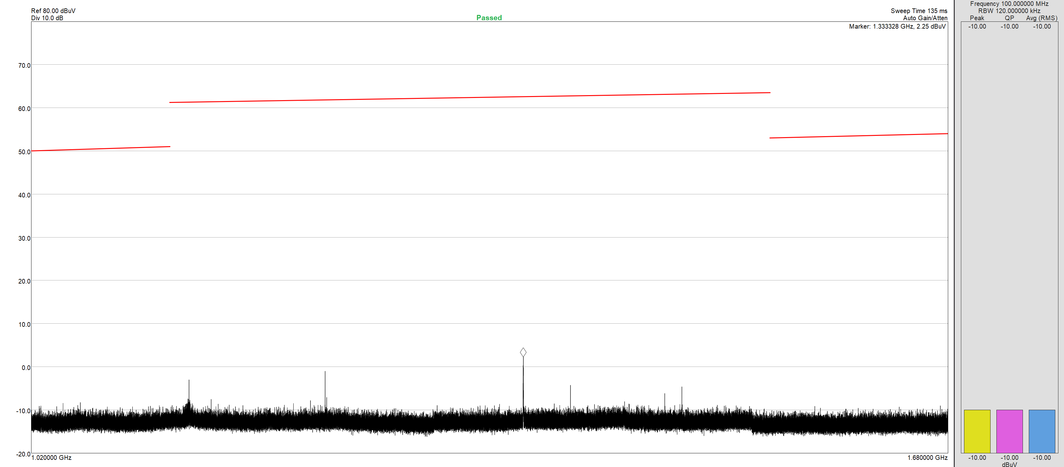
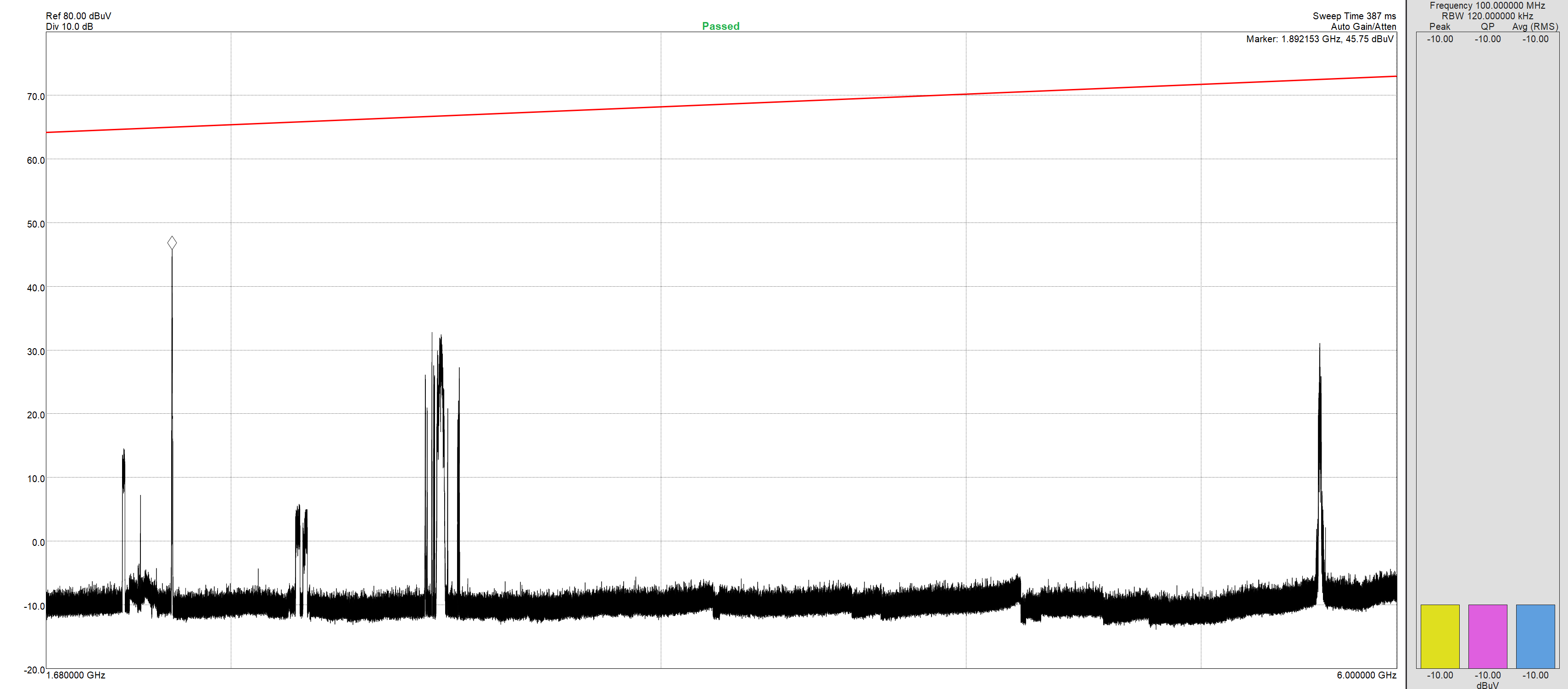
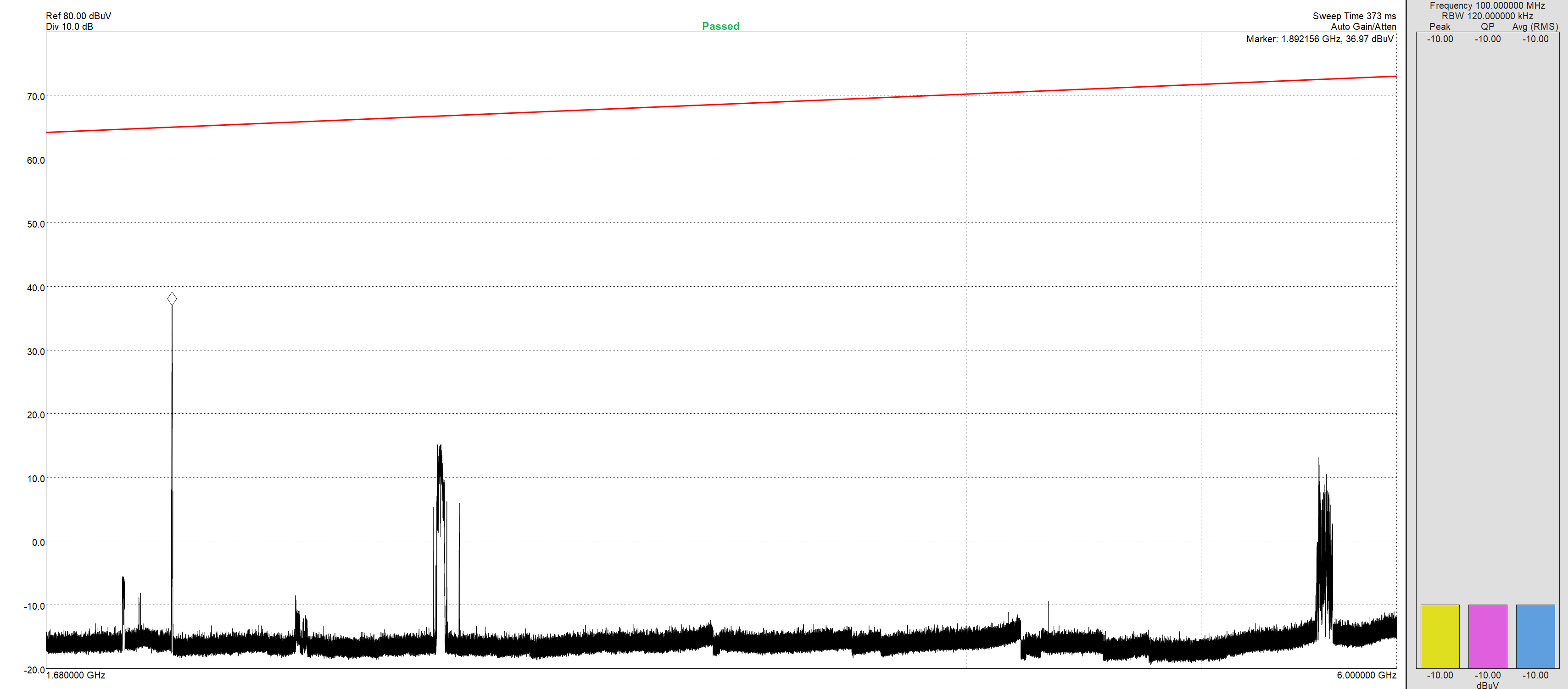
These are some plots of the emissions from our chargers whilst delivering full power. The sweeps are split to align with some of the limit lines above. If you want the full-size images you can click on them.
These higher frequency peaks are actually some local mobile cell towers, a background scan of the same frequency is below for comparison.
As you can see the radiated RF is well below the limits.
However, if we look at some generic plug-in USB chargers as just some low frequencies up to 10MHz, the limit is 40 dBuV, and all of these are way above this.
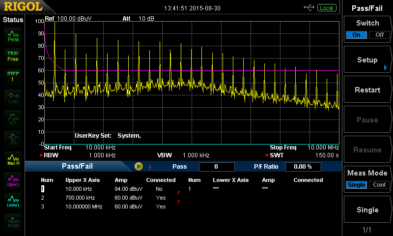
Chinese unbranded dual port marine version
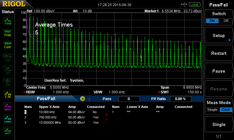
Chinese unbranded mini
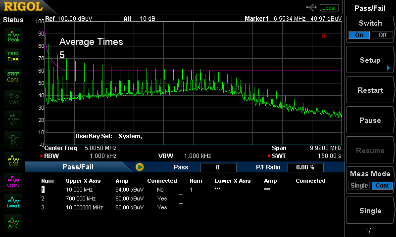
USB Silvercrest SLM charger
These basic readings should help illustrate one of the problems with generic plug-in chargers, they are RF noisy, and can easily cause problems not just with voice communication but the radio navigation systems too including GPS reception.
Remember these graphs are in dB, which is a logarithmic scale, so a small change in reading in dB can result in a large difference in the actual signal level. Very roughly for every 3 dB increase in signal level the actual increase doubles. So a difference of 12 dB between two signals is 16 times, 18 dB is 64 times etc.
Short version
SkyEcho back feeds power onto the USB cable when powered on, against all the USB specifications. This could damage the equipment it is connected to. Whilst it will not damage our chargers, they will not supply power to a SkyEcho if connected when it is turned on. They will, correctly, report the connected device as faulty.
Long version
First some very basic USB power notes. The amount of power a device draws is down to the device. It decides how much to try and draw, based on what the charger says it can deliver. Some chargers say they can deliver 2.5A, and they can. Some say they can deliver 1.0A but they can't, as the current increases, their output voltage drops. The charger should only advertise what it can physically deliver, the client should only draw what the charger says it can deliver.
As a rule, prior to the USB-C connector, power was ‘simple’ and one reason why USB cables have different connectors on each end. The host supplies the power, and the client uses the power. The host (your PC, USB Hub, Plugin charger) has a USB Type-A connector that only connects to a client using a non USB Type-A connector (Mini-B for example). Type-A to Type-A cables is a bad idea as power can be back-fed to the host. For USB-C, this is no longer a problem, as the power delivery is negotiable, either side can source or sink power.
For SkyEcho the USB-C port doesn't look for any kind of specific charger. When plugged in it will try to draw up to 1A, as that is what the battery charging chip is set to do. Nice and simple, but don't plug it into anything that cannot deliver 1A. The charger voltage will drop as it can’t supply the power, or it will overheat. If it is plugged into a USB-C charger, there will probably be no power delivered, as there is no attempt to enumerate/negotiate the level of power required. The charger will, rightly, supply nothing.
It's more interesting if the SkyEcho is powered on before connecting. When powered SkyEcho will supply what looks like the battery voltage (less the voltage drop over a diode) from the USB-C port, it can happily* supply at least 0.5A. After contacting uAvionix this is because the USB-C port is intended to power some as yet unreleased accessories.
Now, this can cause issues. If the charger does what good chargers should do, and check the power on the attached device it will see a voltage there. It will then try to discharge the bus, which it will never do as the SkyEcho is powering the USB-C port. The charger may ignore this and turn on the 5v supply. It may say there is a device connected but not turn the power on. It is totally dependent on how the charger handles this 'error' condition - a client should not back feed a host. For USB-C PD it is mandated to discharge the bus when switching power levels.
* when I say happily, I mean it will, up to a point. If you have an iffy USB cable or connect it to something that can draw more power, I suspect the diode or MOSFET feeding it, preventing the USB-C power from going directly into the battery will probably fail. At 0.5A it was running at ~65 Celsius, as 25 Celsius rise in a couple of seconds, I suspect a short will simply cause the component(s) to fail. If they fail open, that's fine, unless this stops the charging lights from working. If they fail short and the cable is not removed then it will be down to the battery protection to stop bad things from happening unless the PCB tracks or cable fail and break the circuit. There is a lot of power stored in those batteries.


